
Hi all,
New to this forum I come Frex,
I love beautiful mechanical rachetter just a Touareg V10 stuck,
My hobby is the mechanics, I just finished a Porsche Boxster and now I am delighted to put together what V10.
I will used the opportunity to share with you this restoration,
I just started removing pictures here,
Deposited using a motor truck with a pallet made hand, but if you can!,
a technique that I was already using it with my classic Porsche 911.
![Image]()
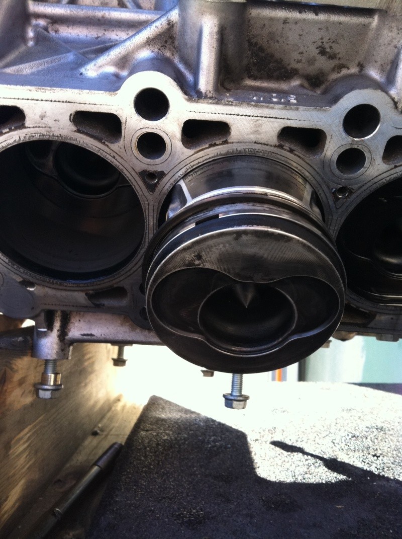
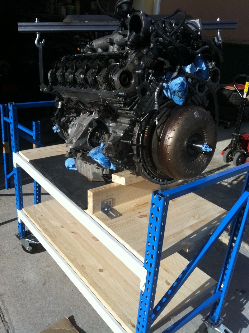
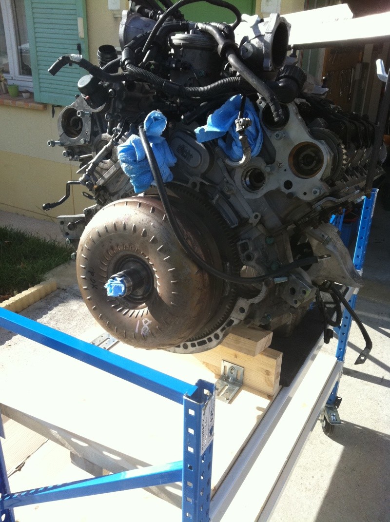
Everything is oversized on this engine,
weight, volume and the place it takes.
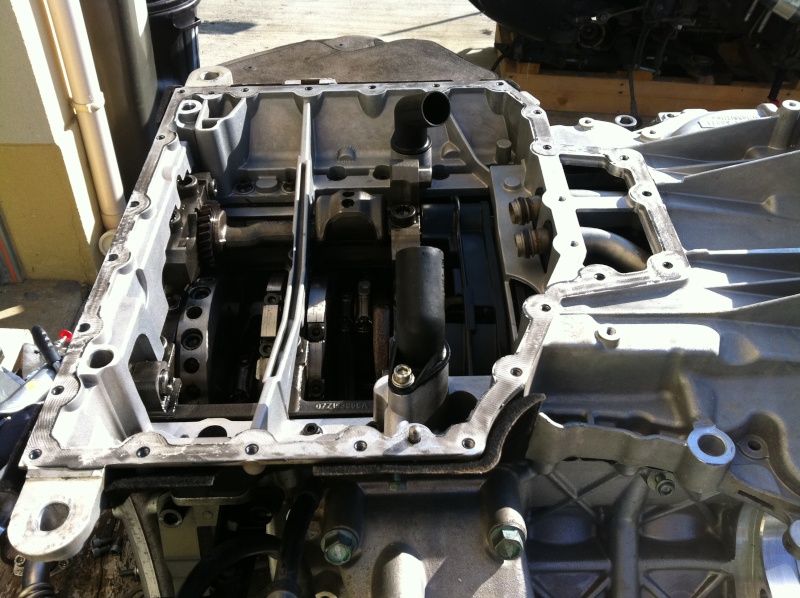
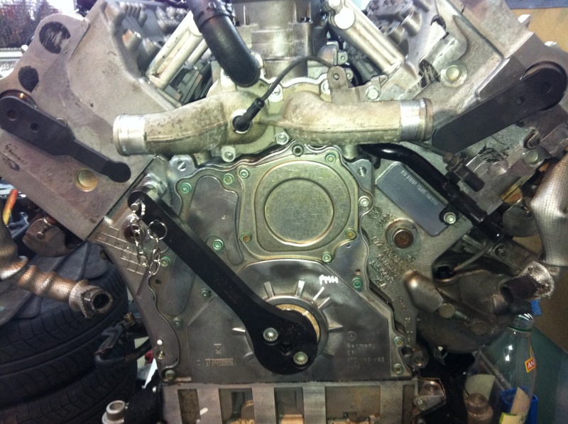
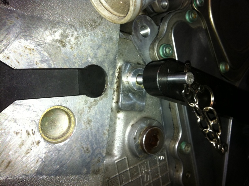
Manufacturing a lifting bar on the separation steps to prepare motor / box
![Image]()
![Image]()
![Image]()
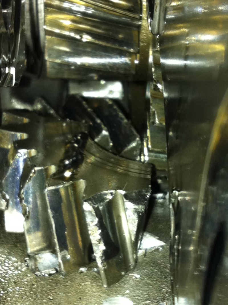
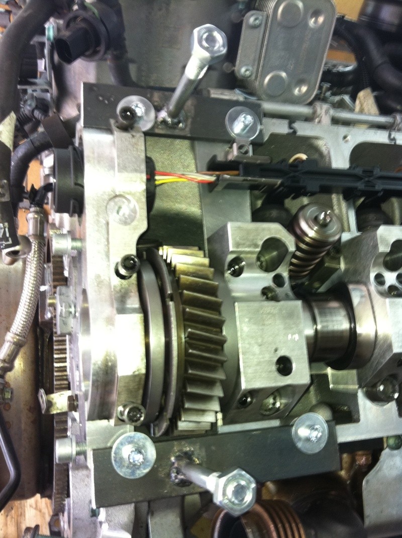
Removing the cylinder head first in search of the crash.
![Image]()
![Image]()
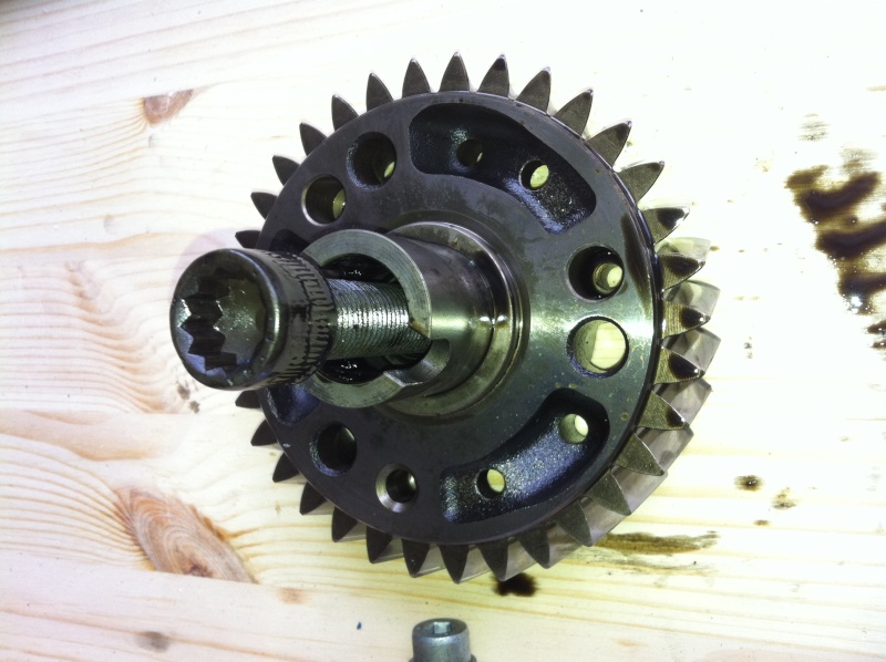
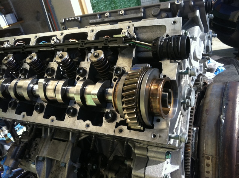
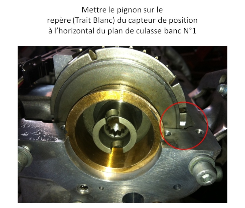
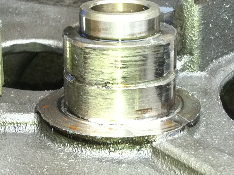
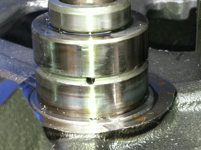
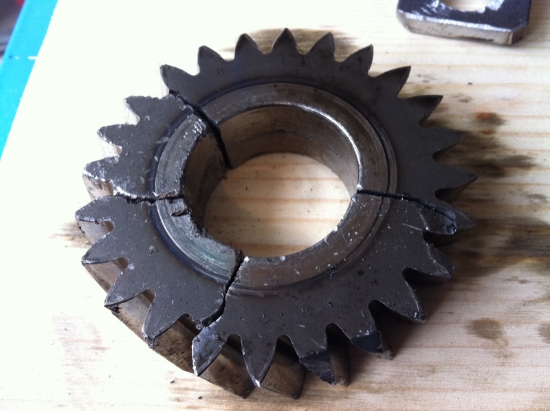
Pinion loose in the eyes of the cylinder head!
No doubt a pinion sold in the housing
the reason the time is still imprésise!
![Image]()
![Image]()
![Image]()
![Image]()
New to this forum I come Frex,
I love beautiful mechanical rachetter just a Touareg V10 stuck,
My hobby is the mechanics, I just finished a Porsche Boxster and now I am delighted to put together what V10.
I will used the opportunity to share with you this restoration,
I just started removing pictures here,
Deposited using a motor truck with a pallet made hand, but if you can!,
a technique that I was already using it with my classic Porsche 911.

Everything is oversized on this engine,
weight, volume and the place it takes.
Manufacturing a lifting bar on the separation steps to prepare motor / box


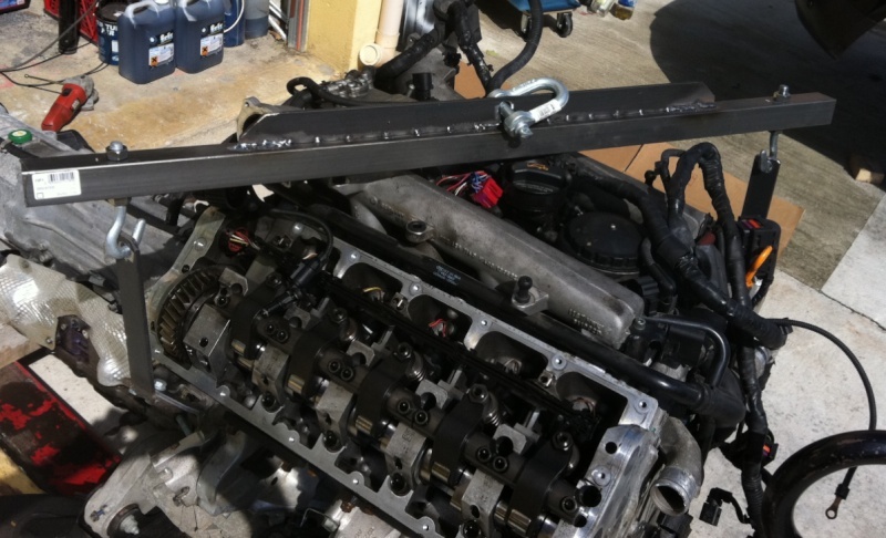
Removing the cylinder head first in search of the crash.
Pinion loose in the eyes of the cylinder head!
No doubt a pinion sold in the housing
the reason the time is still imprésise!