Club Touareg Forum banner

De-pinning Headlight Connector 1J0973897

3.6K views 19 replies 7 participants last post by  PatTouareg  
#1 ·
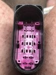
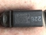
I am seeking advice regarding removal off locking mechanism & de-pinning the 1J0973837 14 pin flat contact housing with contact locking mechanism coupling.
I have a set of VW specific pin release tools, however I cannot release & remove the locking plate. It is internal & has no external release point,
 
#2 ·
I'm wondering if you could use the same tool that is used to remove the female connectors on the coil pack connectors for the gasser vehicles. It works by pushing in the little tabs that click the connector/pins into the connector assembly allowing you to pull them out.
It looks like the one circled in red in the picture below.

Image
 
#5 ·
Per his post, he doesn't have an issue with the terminal removal, but of disengaging the locking mechanism (purple plate).
 
  • Like
Reactions: New2Tregs
#4 ·
You need to move the purple lock down, by disengaging the two tabs at the side. While applying downward pressure on the two posts at the top, compress the two side tabs with a small pick or screwdriver.

Image
 
  • Like
Reactions: Champagne
#6 ·
You need to move the purple lock down, by disengaging the two tabs at the side. While applying downward pressure on the two posts at the top, compress the two side tabs with a small pick or screwdriver.

View attachment 263708
Thank you very much for the information that you have supplied. I should now be able to proceed.
 
#15 ·
If necessary: idd.
Although you can also buy the separate connectors much cheaper.
If you buy what Iachotzfkob suggests, you have to wach out: most of this cable sets are wired for HID headlights ... if you have them, no probem, but if you have Halogen healights you probably have to re-wire them!
 
  • Like
Reactions: lachoradkov
#8 ·
De-pinning connector (mine is 1J0973837), but looks identical.
I only read this this older threat today, having the same question and i would like to add. something:
you do not have to manipulate the 2 little pink tabs! This would for shure damage them.
All you have to do is look inside the connector, you will see an arrow. Slide the whole pink lock plate one millimeter in the other direction than de arrow (not much force is needed and you will hear a click). Now you can remove or insert terminals. Afterwards slide the lock plate in the direction of the arrow, all is good when you hear the click again.
 
#9 ·
I have just revisited the connector with a view to depinning acting upon your advice. It does not work, it is not possible to move the base in the direction of the arrow. The base plate, at the top in the direction of the arrow rests directly against the housing. There is no room for movement, however at the other end there is a substantial gap. T
I did as you suggested, no movement, no noise.
 
#19 ·
So, you did slide the plate in the opposite direction of the arrow to unlock it and you are able to remove the electrical pins so why do you want to remove the plate out of the connector?
I haven’t disassembled that far because I bought new harnesses for $25 from the link I posted above…
Anyway, the connector was assembled somehow, I am not sure but most likely it should be pulled out straight when in the “unlocked” position and de pinned
 
#20 ·
So, you did slide the plate in the opposite direction of the arrow to unlock it and you are able to remove the electrical pins so why do you want to remove the plate out of the connector?
I haven’t disassembled that far because I bought new harnesses for $25 from the link I posted above…
Anyway, the connector was assembled somehow, I am not sure but most likely it should be pulled out straight when in the “unlocked” position and de pinned
Correct: put in unlocked, de-pin and pull out straight.
Although i would not know why anyone would want to do this ...